
- English
- Español
- Português
- русский
- Français
- 日本語
- Deutsch
- tiếng Việt
- Italiano
- Nederlands
- ภาษาไทย
- Polski
- 한국어
- Svenska
- magyar
- Malay
- বাংলা ভাষার
- Dansk
- Suomi
- हिन्दी
- Pilipino
- Türkçe
- Gaeilge
- العربية
- Indonesia
- Norsk
- تمل
- český
- ελληνικά
- український
- Javanese
- فارسی
- தமிழ்
- తెలుగు
- नेपाली
- Burmese
- български
- ລາວ
- Latine
- Қазақша
- Euskal
- Azərbaycan
- Slovenský jazyk
- Македонски
- Lietuvos
- Eesti Keel
- Română
- Slovenski
- मराठी
- Srpski језик
Inspection for Servo Drilling Tapping Milling Cutting Machine
2022-05-05
The fastServo Drilling Tapping Milling Cutting Machine inspection method is fully automated and only takes a few minutes. Before critical machining of high-value parts, they were able to fully verify that the drill-tap-mill machine was operating within tolerance.
The traditional method of calibrating a drill-tap-mill machine requires significant downtime and highly skilled labor. In the past, this meant that drill-tap-mill machines were carefully calibrated at the time of manufacture. A full recalibration is only performed when errors are found in the produced part. In pursuit of higher quality and zero defects, many manufacturers now conduct regular inspections and recalibrations. The improved method can reduce the time required for a typical health check to about 20 minutes and the time required for a full calibration to a few hours. This means that weekly checks and annual recalibrations can be performed. This is an important step forward, although there is still a significant risk of nonconformity.
Another approach is to perform a quick verification test instead of a full calibration. Calibration will quantify each error source independently so that these errors can be compensated. Verification tests, on the other hand, may be sensitive to all error sources without being able to separate them. This means that verification testing will determine when a problem occurs with the machine, regardless of the source of the error. However, it does not enable compensation for this error. Instead, as soon as a problem is identified, calibration must be performed.
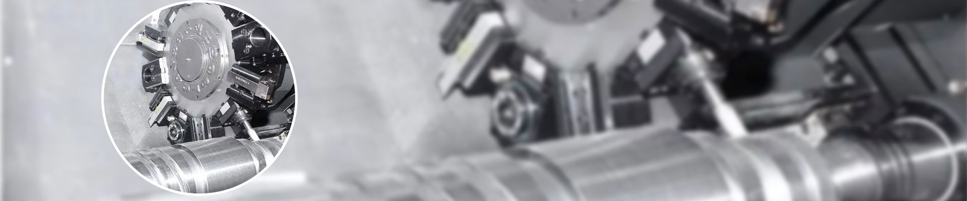
Due to many sources of error,Servo Drilling Tapping Milling Cutting Machines produce inaccurate parts. The most common source is kinematic error. MostServo Drilling Tapping Milling Cutting Machines have many axes in series. For example, a three-axis milling machine has x, y, and z axes. For a given commanded position along one of these axes, there are six possible position errors, corresponding to the six degrees of freedom governing the motion of any rigid body. For example, motion along the x-axis may have translation errors in x due to the x-axis encoder, and translation errors in y and z due to the straightness of the x-axis. Motion along the x-axis can also create rotational errors. Rotation about an axis is often called roll, while two rotations about the vertical axis are called pitch and yaw.
Any position within the machine volume is described by the position of each axis. Therefore, for a three-axis drilling-tapping-milling machine, the nominal position is given by three command coordinates. Since each axis has six degrees of freedom, the actual position is determined by 18 kinematic errors. Often, alignment or straightness between axes is considered alone. Therefore, it is said that there are 21 kinematic errors in the three-axis drilling-tapping-milling compound machine. However, these three straightness errors have only one value for the drilling, tapping and milling compound machine. Other errors depend on position along the axis, so measurements can be made at multiple discrete positions and interpolation between those positions. For a typical machine, approximately 200 individual correction values will be measured in a full calibration.
The traditional kinematic error approach as described above assumes that each axis has an error that varies only with position along that axis and not with position along other axes. This assumption usually yields a sufficiently accurate error correction model. However, there are some effects between the axes, which means that a different approach (volume compensation) can yield higher accuracy.